Hello Friends,
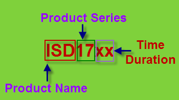
Today I am going to share an interactive project Digital Voice Recorder and Player; based on ISD1700 Series Multi-Message Single-Chip Voice Record & Playback IC. You can store your voice in this chip. Time duration is user selectable.
PinOut of ISD1700 series chip-
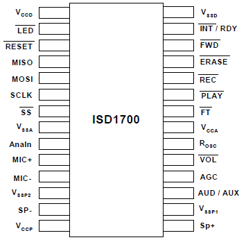
Features :(from datasheet)
1. Integrated message management systems for single-chip, push-button applications.

2. Selectable sampling frequency controlled by an external oscillator resistor.

3. Selectable message duration

4. Message and operation indicators.
5. Dual operating modes-
o Standalone mode:
Integrated message management techniques
Automatic power-down after each operation cycle
o SPI mode:
Fully user selectable and controllable options via APC register and various SPI commands
6. Two individual input channels-
o MIC+/MIC-: differential microphone inputs with AGC (Automatic Gain Control)
o AnaIn: single-ended auxiliary analog input for recording or feed-through
7. Dual output channels-
o Differential PWM Class D speaker outputs directly drives an 8 Ω speaker or a typical buzzer
o Configurable AUD (current) or AUX (voltage) single-ended output drives external audio amplifier.
8. ChipCorder standard features-
o High-quality, natural voice and audio reproduction
o 2.4V to 5.5V operating voltage
o 100-year message retention (typical)
o 100,000 record cycles (typical)
Circuit : The circuit is also given in the Datsaheet.

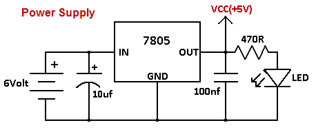
step1: Make this circuit on General Purpose PCB.

Connect a 100k pot at pin20.Adjust it at 80k for sampling frequency of 8KHz.Leave pin 22 open.


stpe2: Connect the Speaker.


step3:Battery setup.Use new cells.


step4:Take a plastic Box according to your PCB size and Fit the circuit inside this.


step5:Ready to use.

Ok! First power on the switch.To record your voice hold down the REC button , while holding this button Green LED indicator continuously on. Now record your voice when green LED will go off that means memory is full.
Now press PLAY button to hear your voice.LED will blink during this.
Now for further recording you have to erase old voice.To erase hold down ERASE button for 4sec.(Remember this step)
Ok again hold REC button to Record.You can record two-three small message and hear both of them by pressing FWD buttton.
Increase and decrease the volume by pressing VOL button.
Adjust 100k pot to set sampling frequency.
NOTE: For more details please refer datasheet.
Downloads :
ISD1700 series Winbond chip-corder
ISD1700 Design Guide
Video:
~pratyush


No comments:
Post a Comment