Hello Friends,
In this article I am going to show how you can turn on and off LEDs just by clicking mouse. For electronics beginners and hobbyist it's very interesting thing to do.This is achieved by PCs Parallel Port. All the LEDs are connected to Parallel Port.
Parallel Port is very popular for building PC controlled applications.You can control DC and STEPPER motors via this port and make A simple robot that will move according to keyboard keys; a relay board that can control Home appliances; AVR Programmer...etc.

Basically Parallel Port is Designed by IBM for connecting Printer to PC hence it is also known as LPT(Line Printer Terminal). It is a 25-pin Port.A 25 Pin D-Type Female Connector is connected at the backside of CPU.
Pin Out of Parallel Port :

All the 25-pins are divided in three sub-ports.Data port,Control port and Status port ; some ground pins are also here.In order to access any port you need Port Address.
Data Port Port Address -- 0x378
Status Port Port Add. -- 0x378+1
Control Port Port Add. -- 0x378+2
port address is written in the software. To know more about Parallel Port go to Reference Link mentioned at the end of this article.
You only need data port pins here.Data port is a bidirectional port.You have to send data in binary Format(1 or 0) to data port. LEDs will be on and off according to your data.Ok! lets make something interesting according to above discussion.
Required Things :
1.A 1m 7-pin Ribbon Cable
2. 25-Pin D-Type male connector
3.6 LEDs
4.6 47om Register


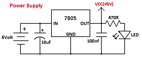
Circuit :

Making Steps:
step1:Cut the 1m 7-pin ribbon.


step2:Solder the ribbon according to circuit.


step3:Take a strip of zero PCB and solder LEDs and registers.


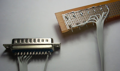

Hardware is completed.

step4:Connect the 25Pin connector to PCs 25Pin connector.

Now comes towards the software part. To control LEDs via parallel port you need a software; the software can be in 'C' or in VB.Here I design the software in VB6 to control the LEDs. Download this software;It is attached with a folder 'PC Controlled LEDs' this folder contain two more files.

There is an important file "inpout32.dll" which is a kernel mode driver for windows freely available at www.logix4u.net. Paste this file in c:\WINDOWS\system32. Double click on LED_control_VB0.1.exe then you get this window.

Click on the buttons and see LEDs on and off in real world.


Downloads:
software LED_control_VB0.1.rar
Video:
Reference : logix4u.net
~pratyush


