Here I am trying to summarize some embedded programming
concepts. If you are new in the field of Microcontroller and embedded system
then you should read this once before going to start programming.
Requirements: Knowledge of ‘C’ programming, Basics of Digital-Electronics
and most important thing is your INTEREST** :)
1.
Data
Types : Standardize data types are defined in the header
file stdint.h
typedef signed char int8_t; Range : -127 to 127
typedef unsigned char uint8_t; Range : 0
to 255
typedef signed char int16_t; Range : -32768 to
32767
typedef unsigned short uint16_t; Range : 0
t0 65535
Ex: uint8_t
x=0;
2.
Number
System :
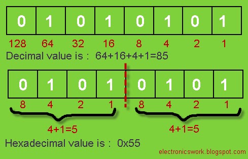
Decimal Number:
ex: 85;
Binary Number: ex: 0b01010101; ‘0b’
represents binary number
Hexadecimal Number: ex: 0x55; ‘0x’
represents hexadecimal number
3.
Shift Operator:
<<
--
Left shift Operator
>> -- Right
Shift Operator
Suppose: x=01010101; or
(x=0x55 ; x=85;)

x=(x<<3); means shift ‘x’
3 times left
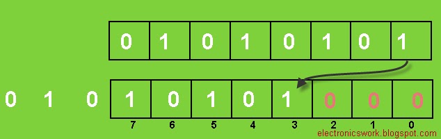
Now x=10101000;
or (x=0xA8; x=200;)
X=(x>>2); means shift ‘x’ two times right
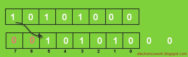
Now x=00101010; or
( x=0x2A; x=200;)
4.
Logical
Operation with bits :
| -
Bitwise OR
& -
Bitwise AND
~ -
Bitwise NOT or One’s Complement
^ - Ex-OR or Toggle Operator
! – Logical NOT
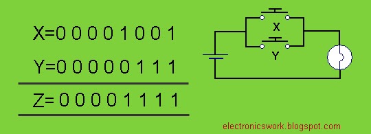
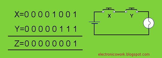
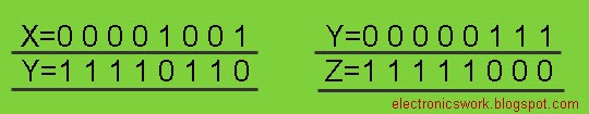
Suppose: X=00001001; and Y=00000111;
a. Z=(X|Y)=00001111;
b. Z=(X&Y)=00000001;
c. Z=~X; Z=~Y;
d. Z=(X^Y)=00001110;
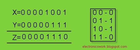
Now you are thinking why we call this “Toggle
Operator”?? Let’s see an example:
Suppose x=1;
while (1) {x=x^1;} then x toggles infinite times

e. Z=!X
!(00001001)=0;
Note:‘~’ and ‘!’ are unary operator.
'!' is logical operator it returns ‘1’ if
value is zero otherwise returns ‘0’.
!(1)=0;
!(236)=0;
!(NON-ZERO)=0;
!(0)=1;
5.
Defining
Macros: Macros are very useful during programming. We have to
define macro at the beginning of the program.
ex: #define
SIZE 5
ex: #define
LCD_PORT PORTD
Suppose we connect LCD port at port D.
In another circuit we connect LCD port at port B then we only have to make
change in one line i.e. in its macro definition.
ex: #define
BEEP PORTB=0X01;\
_delay_ms(500);\
PORTB=0X00;\
We don’t have to write these lines again
and again just write BEEP and we done.
Note: ‘\’
is preprocessor new line character
Ex: For(i=0;i<SIZE;i++);
Whenever we use Macro definition in our
program at compile time it is replaced by its body. (Expanded source code)
6.
AVR
I/O Registers: AVR microcontroller has 8-bit ports and it
deals with 8-bit data. To access any port or pins of AVR microcontroller there
is 3 AVR I/O port access register is defined, these are-
DDRX:
Data Direction Register of port X
PORTX: Data Register on port X
PINX:
Input data register at port X
X is port name it can be
A,B,C or D depends upon Microcontroller.
7.
Write
to Register: Before write data to Data Register we have
to define its Data Direction Register.
1 –
Data out
0 - Data In
Suppose we want to write on port A then we have to write
two lines –
DDRA
= 0b11111111;
PORTA=0b00000001;
or
PORTA=(1<<0);
or
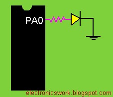
PORTA=(1<<PA0); //PA0 is a macro and it is defined in i/o.h
#define <avr/io.h>
void main()
{
DDRA=0XFF; //all
pins of port A are output pins
PORTA=0X01;
}
//---------------------or----------------------------
#define <avr/io.h>
void main()
{
DDRA=0X01; //PA0
is output pin
PORTA=0X01;
}
//----------------------or-------------------------
//This is the Better Way:
#define <avr/io.h>
void main()
{
DDRA=(1<<PA0); //PA0 is output pin
PORTA=(1<<PA0);
}
//-------------------------------------------------
Note:
SET=1(HIGH) and RESET=0(LOW)
Ex: PORTA=0X03; //set bit 0 and 1, rest is low
Or we can write—
PORTA=(1<<PA0)|(1<<PA1);
“|” operator
is used to add bits.

8. SET and RESET a bit without affecting
remaining bits – only the state of the specified bit is
changed, the previous state of other bit is preserved.
Suppose we write 7 in port A:
PORTA=0B00000111;
Bit
0,1 and 2 is SET rest is RESET. Now if you want to set bit 3 without changing
in previous bits then if you write-
PORTA=(1<<PA3);
Q. what will be the
content of register A??
Answer: PORTA=0B00001000;
Because
you are not adding this bit with port A you are just overlapping the bits of
port A.
The
correct way to do this is –
PORTA=PORTA | (1<<PA3);
or
PORTA|=(1<<PA3);
Now PORTA
becomes PORTA=0B00001111;
In general: To set a bit in register X

Reset a bit: suppose
PORTA=0B00001111; and we want to
reset bit-2.
Now
you are definitely thinking that to reset a bit you will write-
PORTA=(0<<PA2);
THIS IS WRONG. PORTA=(0<<PA2); we cant shift zero. Shifting must be performed
with a non-zero quantity.
NOTE:
We can shift any number except ZERO.
Then
how can we do this?? We can do this indirectly using ‘~’ and ‘&’ operator. See
ex:
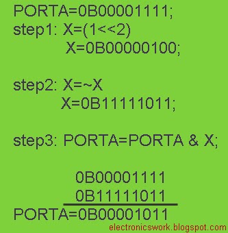
Or we
can write this in one line: PORTA &=~(1 << PA2);
In general: To Reset a bit in port X.

to
be continued…
~Pratyush
Gehlot


