Wednesday, June 15, 2011

§PC Controlled LEDs

Hello Friends,
                     In this article I am going to show how you can turn on and off LEDs just by clicking mouse. For electronics beginners and hobbyist it's very interesting thing to do.This is achieved by PCs Parallel Port. All the LEDs are connected to Parallel Port.

Parallel Port is very popular for building PC controlled applications.You can control DC and STEPPER motors via this port and make A simple robot that will move according to keyboard keys; a relay board that can control Home appliances; AVR Programmer...etc.


Basically Parallel Port is Designed by IBM for connecting Printer to PC hence it is also known as LPT(Line Printer Terminal). It is a 25-pin Port.A 25 Pin D-Type Female Connector is connected at the backside of CPU.

Pin Out of Parallel Port :

All the 25-pins are divided in three sub-ports.Data port,Control port and Status port ; some ground pins are also here.In order to access any port you need Port Address.

Data Port Port Address -- 0x378
Status Port Port Add.    -- 0x378+1
Control Port Port Add.  -- 0x378+2
port address is written in the software. To know more about Parallel Port go to Reference Link mentioned at the end of this article. 

You only need data port pins here.Data port is a bidirectional port.You have to send data in binary Format(1 or 0) to data port. LEDs will be on and off according to your data.Ok! lets make something interesting according to above discussion.

Required Things :
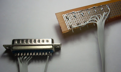
1.A 1m 7-pin Ribbon Cable
2. 25-Pin D-Type male connector
3.6 LEDs
4.6 47om Register


Circuit :

Making Steps:
step1:Cut the 1m 7-pin ribbon.


step2:Solder the ribbon according to circuit.


step3:Take a strip of zero PCB and solder LEDs and registers.


Hardware is completed.
 step4:Connect the 25Pin connector to PCs 25Pin connector.

Now comes towards the software part. To control LEDs via parallel port you need a software; the software can be in 'C' or in VB.Here I design the software in VB6 to control the LEDs. Download this software;It is attached with a folder 'PC Controlled LEDs' this folder contain two more files.

There is an important file "inpout32.dll" which is a kernel mode driver for windows freely available at www.logix4u.net. Paste this file in c:\WINDOWS\system32. Double click on LED_control_VB0.1.exe then you get this window. 
 Click on the buttons and see LEDs on and off in real world.


Downloads:

Video:

Reference : logix4u.net
                                                                                                          ~pratyush

Monday, June 13, 2011

§Digital Voice Recorder & Player

Hello Friends,
           Today I am going to share an interactive project Digital Voice Recorder and Player; based on ISD1700 Series Multi-Message Single-Chip Voice Record & Playback IC. You can store your voice in this chip. Time duration is user selectable.  
I found all the information related to this in the Datasheet ISD1700 SERIES from Winbond. Download this Datasheet from here.
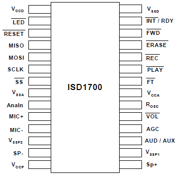
 PinOut of ISD1700 series chip- 


The ISD1700 is designed for operation in either standalone or microcontroller (SPI) mode.Recordings are stored into on-chip Flash memory. Voice signals can be fed into the chip through two independent paths: a differential microphone input and a single-ended analog input. While in Standalone mode, the ISD1700 devices automatically enter into power down mode for power conservation after an operation is completed.In the SPI mode, the user has full control via the serial interface in operating the device.

Features :(from datasheet)
1.     Integrated message management systems for single-chip, push-button applications.

2.     Selectable sampling frequency controlled by an external oscillator resistor.

3.     Selectable message duration : A wide range selection from 20 secs to 480 secs pending upon sampling frequency chosen.

4.     Message and operation indicators.

5.     Dual operating modes-
o Standalone mode:
 Integrated message management techniques
 Automatic power-down after each operation cycle
o SPI mode:
 Fully user selectable and controllable options via APC register and various SPI commands

6.     Two individual input channels-
o MIC+/MIC-: differential microphone inputs with AGC (Automatic Gain Control)
o AnaIn: single-ended auxiliary analog input for recording or feed-through

7.     Dual output channels-
o Differential PWM Class D speaker outputs directly drives an 8 Ω speaker or a typical buzzer
o Configurable AUD (current) or AUX (voltage) single-ended output drives external audio amplifier.

8.     ChipCorder standard features-
o High-quality, natural voice and audio reproduction
o 2.4V to 5.5V operating voltage
o 100-year message retention (typical)
o 100,000 record cycles (typical)

  Circuit : The circuit is also given in the Datsaheet.

Let's Make :
step1: Make this circuit on General Purpose PCB.
 Connect a 100k pot at pin20.Adjust it at 80k for sampling frequency of 8KHz.Leave pin 22 open.

 stpe2: Connect the Speaker.

 step3:Battery setup.Use new cells.

 step4:Take a plastic Box according to your PCB size and Fit the circuit inside this.


 step5:Ready to use.
 
Ok! First power on the switch.To record your voice hold down the REC button , while holding this button Green LED indicator continuously on. Now record your voice when green LED will go off that means memory is full. 
Now press PLAY button to hear your voice.LED will blink during this.
Now for further recording you have to erase old voice.To erase hold down ERASE button for 4sec.(Remember this step)
Ok again hold REC button to Record.You can record two-three small message and hear both of them by pressing FWD buttton.
Increase and decrease the volume by pressing VOL button.
Adjust 100k pot to set sampling frequency.
NOTE: For more details please refer datasheet.

Downloads :
ISD1700 series Winbond chip-corder
ISD1700 Design Guide

Video:


                                                                                                                                     ~pratyush

Wednesday, June 8, 2011

§ Burn AVR Microcontroller Using Parallel Port Programmer

 Hello,
In my previous post I explain how to make AVR Parallel port programmer. Now let’s makes it in use. Requirements-
software side : WINAVR , AVRDUDE , .C file(your code), MAKEFILE
Hardware side : AVR Parallel Port Programmer, Target Board

What is WINAVR?? It is a compiler or open source software development tools for the Atmel AVR series MCUs hosted on the Windows platform. It includes the GNU GCC compiler for C and C++.
What is AVRDude?? it is a program used to burn hex code inside microcontroller. The separate setup of AVRDude for windows is not available actually it is bundled with winAVR compiler.
To burn or program AVR MCU you need a .hex file which is a machine code not human readable only understand by the MCU. WinAVR generates .hex file from code (.c) file. This hex file is then transferred inside MCU using AVR programmer. This hex code is stored in flash memory of MCU. When power gets on; MCU starts doing work according whatever code stored inside flash memory.
First Download and install the latest version of WINAVR in your system.
Target board contains MCU and power supply and ISP (In-System-Programmable) Header. This is a 5-pin header; these pins are programming pins. Different AVR chips have different pinout so please refer the datasheet of the AVR chip.AVR ISP Header has 5 pins which are-RST,MOSI,MISO,SCK,GROUND. 

AVRDude is a command line program, you have to type commands in command window for particular task; for Example -
avrdude –c <programmer type> –p <programmer ID> –p <port> –U flash:w:<PROJECT>.hex 
avrdude –c <programmer type>–p <programmer ID> –p <port> -U hfuse:w:<HFUSE>:m 
avrdude –c <programmer type> –p <programmer ID> –p <port) -U lfuse:w:<LFUSE>:m
Etc. . . .
Don’t Worry! You don’t have to remember all these types of commands, all these commands are bundled in a file called MAKEFILE you have to carry this file in the folder where your .c file is stored. You only have to type short-commands in command window for particular task.

These commands are -
-make all : to generate .hex file it also generate .map.,o..out files.
-make clean : remove the files generated from the command "make all"
-make flash : to program .hex file inside MCU.
-make fuse : to program FUSE bytes.

To calculate fuse bit use very popular AVR Fuse Bit Calculator.

NOTE : Fuses play very important role in the programming; don't try to Experiment with them without proper knowledge; otherwise you can damage your micro controller permanently!!
fuses determine how your chip will act.Refer datasheet for more details.

Step-by-step Explanation -
Step1: Install WINAVR in your System.

Step2: Type your program in notepad and save it with “.c” extension in a folder.
for Example : Program for LED blink
 #define F_CPU 1000000UL  //CPU Speed 1MHz internal
#include <avr/io.h>   
#include <util/delay.h>
void main()
{   
 DDRC = (1 << 5); //PC5 is input ; connect LED at this pin
 while(1){    //loop forever
 PORTC ^= (1 << 5); //Toggle LED at every half second


 _delay_ms(500);
}
}

Step3: Make a folder in c-drive and paste the code "blink.c" in it.
 

Step4:Now paste MAKEFILE in this folder.


Step5: Open make file and do necessary changes in user area ;like project name, MCU type, Port type etc.


 Use this makefile in every project,you only need to change PROJECT name and MCU name."#" symbol is for comment.Things written in right-hand side of "#" is not readable.Here fuses are commented; to make use them remove "#" symbols.Again remember calculate fuses carefully.Ones you set correct fuses you don't have to change them again.In this example i use default fuses of the chip hence no need to set them; hence commented here.

Step6: Open Command prompt.Start->Run->cmd->ok


Step7:Change directories to the location where led_blink (your project folder) is exist.


Step8: Type “make all” and press enter.

Step9:Make your Target-Board.
 

Step10:Connect ISP header in target board.


Step11: Connect Programmer to PC parallel port and power on the supply of target board.


Step12: Type "make flash" in command window.

If all thing is correct then it will show "done" message that means your chip is programmed successfully.


Troubleshooting :
Sometimes you can get this message - 

this message will appear in mostly two cases :
 1.Wire connections on breadboard is not ok, check the connections properly.
 2.Breadboard or Target board power supply is not ON.

If you want to use another AVR microcontroller to burn this code then change the MCU name in MakeFile and recompile this code, if you trying to burn this hex file in another MCU then you will get device signature error because this hex file is compiled for ATmega8.


Downloads :

Video:


                                                                                                                                 ~pratyush

PID Controlled Self balancing Robot using ESP8266 and MPU6050

This ROBOT is made using ESP8266 Node MCU and MPU6050 accelerometer. Motor used here is normal gear motor of 150 rpm with TB6612FNG motor dr...