Monday, December 26, 2011

§Embedded ‘C’ Programming Notes – Part1


Here I am trying to summarize some embedded programming concepts. If you are new in the field of Microcontroller and embedded system then you should read this once before going to start programming. 

Requirements: Knowledge of ‘C’ programming, Basics of Digital-Electronics and most important thing is your INTEREST** :)

1.    Data Types : Standardize data types are defined in the header file  stdint.h
typedef signed char int8_t;               Range : -127  to  127
typedef unsigned char uint8_t;         Range : 0  to  255
typedef signed char int16_t;             Range : -32768  to  32767
typedef unsigned short uint16_t;      Range : 0  t0  65535

      Ex: uint8_t x=0;

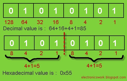
2.    Number System :
Decimal Number: ex: 85; 
Binary Number:  ex: 0b01010101;    ‘0b’ represents binary number
Hexadecimal Number:  ex: 0x55;     ‘0x’ represents hexadecimal number

3.     Shift Operator:
<< -- Left shift Operator
>> -- Right Shift Operator

Suppose: x=01010101;    or     (x=0x55 ;  x=85;)
 
x=(x<<3);   means shift ‘x’ 3 times left


Now x=10101000;    or     (x=0xA8; x=200;)
X=(x>>2); means shift ‘x’ two times right

Now x=00101010;    or    ( x=0x2A; x=200;)
 
4.    Logical Operation with bits :
      | - Bitwise OR
     & - Bitwise AND
     ~ - Bitwise NOT or One’s Complement
     ^ - Ex-OR or Toggle Operator
     !Logical NOT

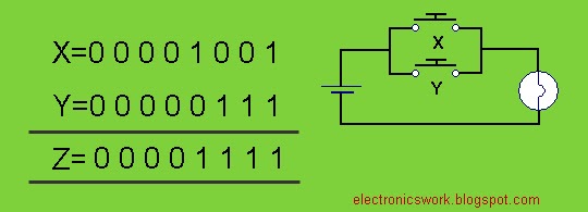
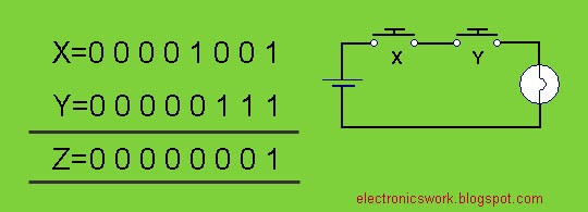
Suppose: X=00001001; and Y=00000111;

a. Z=(X|Y)=00001111;   
b. Z=(X&Y)=00000001;
c. Z=~X;      Z=~Y;
 

d. Z=(X^Y)=00001110;
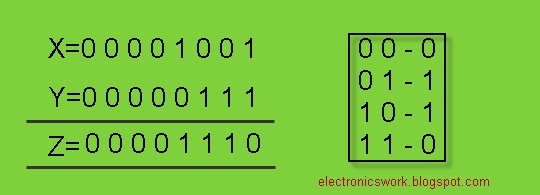
 
Now you are thinking why we call this “Toggle Operator”?? Let’s see an example:

Suppose x=1;     while (1) {x=x^1;}    then  x toggles infinite times
 

e. Z=!X
         !(00001001)=0;

Note:‘~’ and ‘!’ are unary operator.
'!' is logical operator it returns ‘1’ if value is zero otherwise returns ‘0’.
  !(1)=0;
  !(236)=0;
  !(NON-ZERO)=0;
  !(0)=1;


5.    Defining Macros: Macros are very useful during programming. We have to define macro at the beginning of the program.

ex: #define SIZE 5

ex: #define LCD_PORT PORTD
Suppose we connect LCD port at port D. In another circuit we connect LCD port at port B then we only have to make change in one line i.e. in its macro definition.

ex: #define BEEP PORTB=0X01;\
        _delay_ms(500);\
        PORTB=0X00;\
We don’t have to write these lines again and again just write BEEP and we done.
Note: ‘\’ is preprocessor new line character

Ex: For(i=0;i<SIZE;i++);

Whenever we use Macro definition in our program at compile time it is replaced by its body. (Expanded source code)


6.    AVR I/O Registers: AVR microcontroller has 8-bit ports and it deals with 8-bit data. To access any port or pins of AVR microcontroller there is 3 AVR I/O port access register is defined, these are-

DDRX: Data Direction Register of port X
PORTX:  Data Register on port X
PINX: Input data register at port X
X is port name it can be A,B,C or D depends upon Microcontroller.


7.    Write to Register: Before write data to Data Register we have to define its Data Direction Register.
1     – Data out
0     -  Data In

Suppose we want to write on port A then we have to write two lines –

DDRA = 0b11111111;
PORTA=0b00000001;
or
PORTA=(1<<0);
or
PORTA=(1<<PA0);  //PA0 is a macro and it is defined in i/o.h
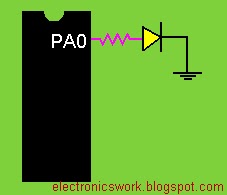
Ex: Write a program to LIT a LED connected at PA0
 
  
#define <avr/io.h>
void main()
 {
   DDRA=0XFF; //all pins of port A are output pins
    PORTA=0X01;
}
//---------------------or----------------------------

#define <avr/io.h>
void main()
 {
   DDRA=0X01; //PA0 is output pin
    PORTA=0X01;
}
//----------------------or-------------------------

//This is the Better Way:
#define <avr/io.h>
void main()
 {
   DDRA=(1<<PA0); //PA0 is output pin
    PORTA=(1<<PA0);
}
//-------------------------------------------------


Note: SET=1(HIGH)   and  RESET=0(LOW)
Ex: PORTA=0X03;    //set bit 0 and 1, rest is low
Or we can write—
PORTA=(1<<PA0)|(1<<PA1);
“|” operator is used to add bits.
 

8.    SET and RESET a bit without affecting remaining bits – only the state of the specified bit is changed, the previous state of other bit is preserved.

Suppose we write 7 in port A: 
PORTA=0B00000111;
Bit 0,1 and 2 is SET rest is RESET. Now if you want to set bit 3 without changing in previous bits then if you write-
PORTA=(1<<PA3);

Q. what will be the content of register A??
Answer: PORTA=0B00001000;

Because you are not adding this bit with port A you are just overlapping the bits of port A.

The correct way to do this is –
PORTA=PORTA | (1<<PA3);
or
PORTA|=(1<<PA3);
Now PORTA becomes PORTA=0B00001111;

In general: To set a bit in register X
 

Reset a bit: suppose PORTA=0B00001111; and we want to reset bit-2.
Now you are definitely thinking that to reset a bit you will write-

PORTA=(0<<PA2);

THIS IS WRONG. PORTA=(0<<PA2);  we cant shift zero. Shifting must be performed with a non-zero quantity.

NOTE: We can shift any number except ZERO.

Then how can we do this?? We can do this indirectly using ‘~’ and ‘&’ operator. See ex:
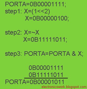
 
Or we can write this in one line:  PORTA &=~(1 << PA2);

In general: To Reset a bit in port X.
 

to be continued…


                                                                                                                 ~Pratyush Gehlot

Wednesday, December 21, 2011

§5X7 Scrolling Message Display

Hello Friends,
     LED Matrix displays are very popular for displaying messages you can see them in everywhere in your daily routine. For example at railway station - it is used to display train details, in buses, at restaurants etc. In this post we will make a simple 5x7 LED matrix display and display some messages.

5x7 LED display needs 35 LEDs to make it. We have to connect all of 35 LEDs with a single microcontroller; here I am using AVR atmega8 which has 28 pins. If one LED takes one I/O pin of MCU then 35 LEDs required 35 I/O pins but atmega8 have only 22 I/O pins. Then how we do this??

Answer is MULTIPLEXING. This technique requires fewer I/O pins of MCU. We need only 12 I/O pins of MCU to interface this display. To understand that techniques see the figure below.


You can see in the figure that there are 5 column and 7 rows. All the cathodes are shorted horizontally and all the anodes are shorted vertically. All the anodes are controlled by columns and all the anodes are controlled by rows. This structure makes a matrix of 7x5 hence the name ‘LED Matrix display’ and controlling all the LEDs using this technique called multiplexing.

For example: If we want to ON led located at (0, 0) then we have to connect first column to VCC and first Row to Ground. We will discuss more about this in this post.

Ok! First we have to make this matrix; this requires patience and lots of time to soldering. See the pics below.

 
This is my 13x5 LED matrix.

 
Be careful to make this; the directions of all the anodes and cathodes should be in correct way otherwise some LEDs will not glow. You can see in the figure that there is a bridge shape structure which is complex and many chances to shorting; If you hesitate to make this then don’t worry there is readily available 5x7 LED display available in the market.See pic below :

 
This is a 5x7 LED Matrix module common anode type. Let’s see its pin sequence.


Circuit Diagram :
 
 We can't connect LEDs directly to supply hence we have to connect resistance within its path, 470 ohm is sufficient with 5volt supply. Here I am using MCU as current sinking so for current sourcing I placed 4 NPN transistors at columns. Base of transistors are connected to MCU. When base goes high Emitter to Collector gets shorted and vcc comes at columns.

Readily available 5x7 LED modules have no regular sequence of row and columns so we have to spend some time with PCB and soldering iron. 

Take a small piece of zero PCB and make a Header Board for this LED module. Also place transistors and registers on it. See images –

 
Connect a 12 pin female burg strip for Row and Column Connection.


Now we can directly connect this with our microcontroller. The purpose of making this is to make it portable so that we can connect it on the breadboard also. Always try to make things portable so that we don’t have to make them again if repeated.

Make two ribbon cables. One is 7 pin male-to-male and second is 5 pin male-to-male. See pics :

 
Connect the cables to 5x7 module and to Microcontroller with the help of circuit diagram.


Hardware part is completed. Let’s move towards software part.


To display a character break it in five 8-bit binary (or hex) sequences. See the image below-
 

                                              1 -- LED ON      0 -- LED Off
(Note : We configure MCU as current sinking so we have to send invert sequence ~seq[] )

Store the sequences in an array.We have to switch column one by one rapidly. Binary sequence comes from micro-controller strikes at row pins (R1-R7) and that time if any column line is active (High) then this sequence will show on that column. We have to send seq1 to col-1, seq2 to col-2 and so on. If you don't understand clearly then see the image blow, which is self explanatory.
Columns are switched one by one with some delay and at the same time binary data comes at row will display on that column line.

**What will happen if we decrease column switching delay (or increase switching speed)?  Yes, you are thinking right we will see a still image. This phenomenon is known as “Persistence of Vision”, it gives the illusion that all the LEDs lit at the same time. This is the basic concept of this display. See the image below –

See the image below - POV effect
 
Program: To display a single character
MCU : Atmega8 @ 16MHz  Compiler – WinAVR

Code :
#define F_CPU 16000000UL
#include<avr/io.h>
#include<util/delay.h>

unsigned char seq[]={
0b01111111,
0b00001001,
0b00001001,
0b00001001,
0b00000110,  
};
                    
int main()
{   
   DDRC=0xFF;
   DDRD=0xFF;
   PORTC=0;
   PORTD=0; 
   int i=0;
    while(1)
       {   
          for(i=0;i<5;i++)
           {  
           PORTC=(1<<i);       
           PORTD=~seq[i];
           _delay_ms(3);           
        }
  }
 return 0;
}

Program -2: Scrolling Message

The 5x7 hex sequence of all the characters are stored previously in a header file “font5x7.h” just include it in your main program and enjoy it. All the characters are stored at its ascii location. So first convert characters in its ascii value to fetch up sequence from correct location.

To display moving message we have to maintain a buffer and store binary sequences of all the characters of our message in it. A window of sequence 5 will slide continuously at specified time which will show moving effect.(see ISR section of the code)

Software delay is not accurate so I configure AVR internal Hardware Timer which is CPU independent. I am using 16-bit Timer1 in compare mode means I can decide it’s counting boundary according to my requirement. If you are not familiar with timer go through AVR datasheet or Google it.

Let’s do some calculation:
A good POV frequency is 400Hz (Flicker Free). Our CPU frequency is 16000000Hz and timer frequency is F_CPU/Prescaler=(16000000/1024)=15625Hz.
So compare value to generate 400Hz is ---
Compare Value = (15625/400)=39.0625
1/400=2.5ms delay means at every 2.5 ms timer interrupt will strike ISR. 


Code :
#define F_CPU 16000000UL
#include <avr/io.h>
#include <util/delay.h>
#include <avr/interrupt.h>
#include "font5x7.h"

#define LED5x7_DDR DDRD
#define LED5x7_PORT PORTD

#define LED5x7CONTROL_DDR DDRC
#define LED5x7CONTROL_PORT PORTC 

unsigned char buffer[];
unsigned int buffer_loc=0;
volatile int count=0,scroll=0,col=0;

//----------------------------------------------------------------
void Scroll_MSG(char *msg)
{
 int i,j=0;
 while(*msg!='\0')
 {
    j=(*msg-32)*5;
      for(i=j;i<(j+5);i++)
       {  
          buffer[buffer_loc]=font5x7[i];
          buffer_loc++;
        }
       buffer[buffer_loc]=0;
      buffer_loc++;
      msg++;
 }
}
//----------------------------------------------------------------
void Timer_Init()
{
    TCNT1=0;
    TIMSK|=(1<<OCIE1A);
    OCR1A=39;
    TCCR1B|=(1<<CS12)|(1<<CS10)|(1<<WGM12);//F_CPU/1024,CTC
    sei();
}
//----------------------------------------------------------------
int main()
{
Timer_Init();

LED5x7_DDR = 0xFF;
LED5x7CONTROL_DDR = 0xFF;

Scroll_MSG(" 5x7LED DISPLAY");
Scroll_MSG(" By-PRATYUSH ");

while(1);
return 0;
}
//----------------------------------------------------------------
ISR(TIMER1_COMPA_vect)
{
 count++;
 if(count==50){ //to increase scrolling speed decrease counting
   count=0;scroll++;
    if(scroll>buffer_loc-5)
     {scroll=0;}
  }

 LED5x7CONTROL_PORT = (1<<col);
 LED5x7_PORT = ~buffer[scroll+col];

 if(col++==4)
      {col=0;}
}
//----------------------------------------------------------------

My Pocket Electronic Message card: :)

 
Downloads:  circuit diagram 
                      hex file and code for display single character
                      hex file and code for scroll string/message

Video: 
                                                                                                                             ~Pratyush Gehlot

Sunday, December 4, 2011

§ Interfacing HD44780 LCD – Part3

Hello Friends,

                  In this post I am going to share my 16x2 LCD library Functions with you. This library will help you to easily interface 16x2 LCD with AVR. In my previous two posts I explain the internal operation of LCD and the concept to print characters on LCD. In the last post I also explain three main functions-

1.      Send_LCD_Char(uint8_t data);
2.      Send_LCD_Cmd(uint8_t data);
3.      LCD_init();

Using first two functions I write some other functions which will help you to pickup more command on  this LCD. Here I am going to explain these functions one by one –


§ Move the cursor at specified location on the screen:


DDRAM area Highlighted in green is responsible to show characters on LCD. We have to move cursor in this area means to print any character on LCD we have to first set the DDRAM address or location where our character will be print. To access DDRAM there is some commands –

 
For LCD 1st Line at (0, 0) -> 0x80
For LCD 2nd Line at (0, 1) -> 0xC0

If we want to move cursor at (1,1) then we have to send command: (0xC0+1)
Or in practical way we have to write:  Send_LCD_Cmd(0xC0 + 1 );

To move cursor at any location on the screen I write a function:
LCD_gotoxy(uint8_t  x, uint8_t  y);

#define LCD_1ST_LINE     0x80
#define LCD_2ND_LINE     0xC0

void LCD_gotoxy(uint8_t x, uint8_t y)
{
  if(!y)Send_LCD_Cmd(LCD_1ST_LINE  + x);
  else Send_LCD_Cmd(LCD_2ND_LINE  + x);
 }

Example : LCD_gotoxy(4,0);

 
§ Print a Character on LCD:  I already discuss this topic and it’s Function in my previous post. 

      Send_LCD_Char(uint8_t  data);

Ex. Send_LCD_Char(‘P’);

 
 If you want to print this character at (4,0) then :

  LCD_gotoxy(4,0);
  Send_LCD_Char(‘P’);


§ Print a String on the screen at specified location:  Now you can easily make a function for print a string using previous two functions.

     void LCD_printStr(uint8_t x,uint8_t y,char *s);
   
     Ex. LCD_printStr(0,0,”PRATYUSH”);

 
void LCD_printStr(uint8_t x,uint8_t y,char *s)
{
   LCD_gotoxy(x,y);
     while(*s)
      Send_LCD_Char(*s++);
 }


§ Print Numbers on LCD: This LCD is a character LCD we have to send ascii value of a character. If we want to print ‘0’ then we have to write :

                                    Send_LCD_Char(48);  or  Send_LCD_Char(‘0’);

But if we want to print 123 then?? Using a small trick in ‘C’ we can do this. We have to first break our number in digits then on by one send the ascii values of these digits on the screen. I write a function for displaying a number on the screen at specified location of specified length:

void LCD_printInt(uint8_t x,uint8_t y,uint8_t len,uint16_t n);

len - length (should be <=5)
n   - Integer number

Ex.  void LCD_printInt(4,0,3,123);


void LCD_printInt(uint8_t x,uint8_t y,uint8_t len,uint16_t n)
{
char num_arr[5]={0,0,0,0,0};
int i=len-1;

 while(n)
 {
   num_arr[i--]=n%10;
   n=n/10;
  }
 LCD_gotoxy(x,y);
 for(i=0;i<len;i++)
  {
   Send_LCD_Char('0' + num_arr[i]);
   }
}


Note : If you write: LCD_printInt(4,0,2,1234); then it will display ‘34’ on the screen. So remember to set correct length in the function.


§ Clear the screen: 

LCD_clr();

void LCD_clr()
 {
   Send_LCD_Cmd(0x01);
  }


§ Print Custom Characters: (user define characters)
In my previous post I explain that CGRAM is used to store user define characters. We have to store the bitmap images of these characters in CGRAM area starts from 0x40. In DDRAM location 0 to 7 is reserved as address of custom characters.

** If you write: Send_LCD_Char(0);  then it will print custom character from location 0 of DDRAM.We have 7 locations in DDRAM so we can store maximum of 7 custom characters at a time.

 
To load custom character use the function below :

Load_CustomChar(const uint8_t *cc,uint8_t loc);

Ex: Load_CustomChar(cc0,0);


const uint8_t cc0[8]={21,10,21,10,21,10,21,0};

void Load_CustomChar(const uint8_t *cc,uint8_t loc)
{
 uint8_t i;
 Send_LCD_Cmd(0x40+(loc*8));//Address where custom character is stored

    for (i=0;i<8;i++)
    {
      Send_LCD_Char(cc[i]);
     }
     _delay_ms(10);
}
cc0 is a array which contain bitmap image of custom character.


§ Scroll LCD Screen:You can scroll LCD display in left or right using two commands:

 SHIFT_DISP_RIGHT  -  0x1C
   SHIFT_DISP_LEFT   -  0x18

void Scroll_LCD()
 {
  uint8_t s;
  for(s=0;s<8;s++)
  {
  Send_LCD_Cmd(SHIFT_DISP_RIGHT);
  Delayms(300);
  }
 for(s=0;s<8;s++)
  {
  Send_LCD_Cmd(SHIFT_DISP_LEFT);
   Delayms(300);
  }
 }
Ex.Scroll_LCD();

 
§ Animation on LCD: Using custom characters you can design interactive animation. Here I am going to share a Function in which you can display a bar and fill its pixels.

 Draw_Bar( uint8_t  x, uint8_t  y, uint8_t  len, uint8_t  pxl );

x,y- is the location where you want to show bar
len – is the length of bar
pxl – how many pixel you want to fill


void Draw_Bar(uint8_t x,uint8_t y,uint8_t len,uint8_t pxl)
{
 Load_custom_bars();
 int i,cc;
 LCD_gotoxy(x,y);
 for(i=0;i<len;i++)
  {
   if(((i*5)+5)>pxl)
    {
     if((i*5)>pxl){cc=0;}
     else{cc=pxl%5;}
     }
   else {cc=5;}
   Send_LCD_Char(cc);
   _delay_ms(2);
  }
}

Ex. Draw_Bar(0,0,12,26);
 Output:


§Using LCD library:
//---------------------------------------------------------------------------
//***************16x2 HD44780 LCD DRIVER ************************************
// File Name  :  ew_lcd.c
//Target MCU  :  ATtiny2313,ATmega8,ATmega16/32 @ 16MHz
//  Compiler  :  WinAVR
//    Auther  :  Pratyush Gehlot, Rajasthan, India
//      Blog  :  www.electronicswork.blogspot.com
//***************************************************************************
//---------------------------------------------------------------------------

Step1. Copy LCD Library file ‘ew_lcd.c’ in your project folder.
Step2. Include this file in main code file Ex. #include “ew_lcd.c”
Step3. Initialize lcd in main program. Ex. LCD_init();

Circuit Diagram:
 
Tutorial 1:  Program to display some text on screen – 

Code:
#define F_CPU 16000000UL
#include <avr/io.h>
#include <util/delay.h>
#include "ew_lcd.c"

int main(void)
{
 LCD_init();
  LCD_printStr(0,0"HELLO!");
    LCD_printStr(2,1,"I AM HD44780");
   }
 return 0;                         
}
Output:


Tutorial 2: Display Custom characters

Code:

#define F_CPU 16000000UL
#include <avr/io.h>
#include <util/delay.h>
#include "ew_lcd.c"

const uint8_t cc0[8]={21,10,21,10,21,10,21,0};//chess
const uint8_t cc1[8]={0,27,27,0,4,17,14,0};//smily
const uint8_t cc2[8]={16,24,28,30,28,24,16,0};//arrow
const uint8_t cc3[8]={31,31,31,31,31,31,31,0};//block
const uint8_t cc4[8]={0,31,28,28,28,28,31,0};//bar
const uint8_t cc5[8]={31,17,17,17,17,17,31,0};//rectangle
const uint8_t cc6[8]={31,31,31,27,31,31,31,0};//hole
const uint8_t cc7[8]={0,10,10,0,17,14,6,0};//happy

void Load_CustumChars()
{
 Load_CustomChar(cc0,0);
 Load_CustomChar(cc1,1);
 Load_CustomChar(cc2,2);
 Load_CustomChar(cc3,3);
 Load_CustomChar(cc4,4);
 Load_CustomChar(cc5,5);
 Load_CustomChar(cc6,6);
 Load_CustomChar(cc7,7);
 }

int main(void)
{
 LCD_init();
 Load_CustumChars();
 LCD_printStr(0,0,"Custom Character");
 int i;

 while(1){
  for(i=0;i<8;i++)
  {
   LCD_gotoxy(i*2,1);
    Send_LCD_Char(i);
   }
  }     
      
Output:


Tutorial 3: Bar Animation

Code:
#define F_CPU 16000000UL
#include <avr/io.h>
#include <util/delay.h>
#include "ew_lcd.c"

int main(void)
{
 LCD_init();
 int i;

 while(1){
  LCD_printStr(0,0,"Loading...  %");
   for(i=0;i<80;i++)
    {
      Draw_Bar(0,1,16,i);
       LCD_printInt(10,0,2,i);
    }
   }
 return 0;                         
}
                   

Output :(screenshot)
 
Downloads: 
LCD Driver : ew_lcd.c
Tutorial 1 Files
Tutorial 2 Files
Tutorial 3 Files

Video:

                                                                                                                           
                                                                                                                ~Pratyush Gehlot

PID Controlled Self balancing Robot using ESP8266 and MPU6050

This ROBOT is made using ESP8266 Node MCU and MPU6050 accelerometer. Motor used here is normal gear motor of 150 rpm with TB6612FNG motor dr...