Hello Friends,


Sensor Setup - 2


After a long delay, now again I am ready to post some
interesting projects. Here I am sharing automatic Railway Gate control system
using AVR micro controller. Gates will close automatically when train arrival
and open when train departure from crossing. The main purpose of this project is to avoid
accidents and save time.
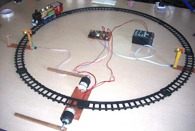
This project utilizes Two IR Tx./Rx. Pair is placed at either
side of the gate with some distance as shown in the pic above. When train cuts first sensor light
signal toggled from Green to Red; a buzzer gets activated for 2 seconds and
railway gate will closed. When train cuts second sensor then a countdown timer
starts and when it counts zero light signal again toggled from Red to Green ;
again buzzer gets activated for 2 Seconds and gates will closed. Timing for
countdown timer is set in the controller according to the speed and length of
the train. You can easily measure this timing for your toy train. I made this
bidirectional so train’s direction doesn’t matter.
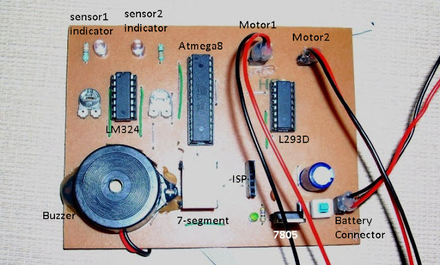
I design circuit using AVR ATmega8 microcontroller.IR sensors output is connected to comparator LM324.LM324 generates TTL High/Low signal at its output pins which is fed to MCU's pins as Input. According to input from LM324 Micro-controller take action. Two DC Motors is used for controlling the gate, these motor's current requirement is much more then MCU hence we need a Motor Driver IC L293D.
Required Components:
1.DC Geared Motors RPM:30 - 2
2.IR Tx./Rx. Pairs - 2
3.MCU ATmega8 - 1
4.IC-LM324 - 1
5.IC-L293D - 1
6. Registers 470E - 10,10K-2,4.7K-1
7.Capacitors : 1000uF.16volt -1 , 100nF-1
8.Seven Segment CC - 1
9.Some LED's : 2- Green, 2-Red, 3 others
10.7805 -1
11.6Volt,4.5MAh Battery
12.some wires, burg strips etc.
and a Toy Train --
Circuit Diagram:
Making:
step 1 : First make the sensor setup.IR Tx./Rx. should be connected in line of sight. Two signal LEDs. Total five wire comes out from this sensor setup- VCC, GND, Sensor Output, Red LED anode, Green LED anode. Distance between IR Tx./Rx. is about 12cm.
Sensor Setup - 1
Sensor Setup - 2
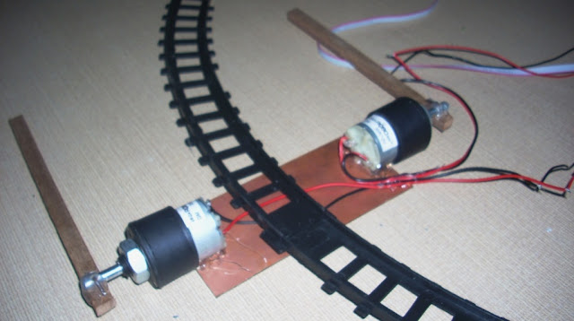
Step:2 Gear Motor's setup.
Step:3 Circuit design. I design the layout in PCB-Wizard.
Step:4 Whole setup -
See Video for more clarification.
Software : source code is written in C. MCU - Atmega8 @1MHz internal.Compiler - WINAVR.
#define F_CPU 1000000UL
#include <avr/io.h>
#include <util/delay.h>
#define CUT1 bit_is_clear(PIND,0)
#define CUT2 bit_is_clear(PIND,1)
#define BEEP PORTD|=(1<<PD4);\
delayms(1500);\
PORTD &=~(1<<PD4);\
#define MOTOR_CW PORTC = 0B00111010;\
delayms(800);\
PORTC=0X00;\
#define MOTOR_ACW PORTC = 0B00110101;\
delayms(800);\
PORTC=0X00;\
#define RED_ON PORTD|=(1<<PD6);\
PORTD&=~(1<<PD7);
#define GREEN_ON PORTD|=(1<<PD7);\
PORTD&=~(1<<PD6);
char seg[10]={0x3F,0x06,0x5B,0x4F,0x66,0x6D,0x7D,0x07,0x7F,0x6F};
void delayms(uint16_t ms){
while(ms){
_delay_ms(1);
ms--;
}
}
int main()
{
DDRC = 0xFF;//All Outputs
DDRB = 0xFF;//All Outputs
DDRD = 0XF0;//PD0,PD1 Inputs,PD4-PD7 Outputs
PORTD|=(1<<PD0)|(1<<PD1);//Internal Pull Ups
int i,done;
while(1){
done=0;
GREEN_ON;
PORTB=0X00;//Segment OFF
if(CUT1){
BEEP;
while(CUT1);
while(!CUT2){RED_ON;if(!done){MOTOR_CW;done=1;}}
if(CUT2){for(i=9;i>=0;i--){PORTB=seg[i];delayms(700);}
BEEP;GREEN_ON;MOTOR_ACW;
}
}
if(CUT2){
BEEP;
while(CUT2);
while(!CUT1){RED_ON;if(!done){MOTOR_CW;done=1;}}
if(CUT1){for(i=9;i>=0;i--){PORTB=seg[i];delayms(700);}
}
if(CUT2){
BEEP;
while(CUT2);
while(!CUT1){RED_ON;if(!done){MOTOR_CW;done=1;}}
if(CUT1){for(i=9;i>=0;i--){PORTB=seg[i];delayms(700);}
BEEP;GREEN_ON;MOTOR_ACW;}
}
}
return 0;
}
}
return 0;
}
After making this project I realize some limitation, first it required
different type of IR sensors which should not detect human interrupt and second
thing is at gate closing time if any vehicle present in between and below the
gate then gate should detect the presence of any vehicle or obstacle. If you
resolve these then please share.
Downloads:complete code + hex file
Video:
~Pratyush


Hey bro , this is Pias . I want to make this project , Can you send me the hex file and '.pcb' file of circuit diagram to my mail id ? If you It will be great favour for me .
ReplyDeletemnhpias@gmail.com
Best regards .
i dont want to use the buzzer and 7segment display..what changes should i make in the program??
ReplyDeleteDonot make any changes in it dear,
Deleteits your choice t put buzzer and 7-segment display....
The program donot effect the circuit...
can u mail me too the .pcb file and a detailed info for the project? my id is sanu_gopa@yahoo.co.in
ReplyDeletecan u mail me how to interface this model with computer interface? my id is vanands@rediffmail.com
ReplyDeletecan u plz send me the circuits and code to my mail albinvadakkekara@gmail.com
ReplyDeletehow should i get it burnt into the chip???? niharikachandu@yahoo.co.in
ReplyDeleteHello...pratyush...
ReplyDeletenice to see ur blog...also tht u r too from jecrc jodhpur...
gud job..
m arjun of 2008 batch ECE,,
keep rocking \m/
Hey,I want to make this project , Can you send me the hex file and '.pcb' file of circuit diagram to my mail id ? If you It will be great favour for me .
ReplyDeleteabhisheksuhan@gmail.com
Hai brother this is bharanidharan. I am going to the project on this topic. Will you help me in doing this within three days. Can I use IC8051 for this project. please give some ideas on this to my mail-id. my mail-id is bharanidharanbabukpm@gmail.com . I am waiting for a positive response from you.
ReplyDeletehey can you plz help me to do a project? My project is about automatic car space management system . I had got the circuit from the EFY. But making the gate is too difficult. So can you plz make some change in that one (adding the L293d) for motor controller. I will send you the circuit and code to you mail id. Plz send ur mail id to me albinvadakkekara@gmail.com
ReplyDeletehis email id is :- pratyushgehlot@gmail.com
ReplyDeleteHI, I WANT THE HEX FILE OF THIS PROGRAM... PLEASE MAIL ME THE HEX FILE TO MU EMAIL ID..
ReplyDeleteEmail id:- hkumar136@gmail.com
hello sir. on which principle sensor is woking in this project?????????
ReplyDeletehello sir....
ReplyDeleteplzzz tell me that which type of sensor is used in project and also send me the working principle of sensor....
email id=nomanali000188@yahho.com
Hello sir,
ReplyDeleteI made the same project that you did but we had a problem its not working. we had a problem in connecting the ISP header please brief me,
please send the pin details of ISP header.
email id sandeepreddylethakula@gmail.com
Hey! I want to make this project for science fair can u send me the details to my mail barani.prasath.kvk@gmail.com
ReplyDeletehi everyone, now you can download code and hex file.
ReplyDeletehey bro....my self jay choksi...i want to make this project.....can you send me the project all details.........and ISP header explai briefly and please send the pin deails of ISP header........my email id:- jaychoksi96@gmail.com............pls bro send all details........i m waiting positive response..............pls send bro...all details.............
Deletethanxs :)
DeleteHey bro , this is mohan . I want to make this project , Can you send me the hex file and '.pcb' file of circuit diagram to my mail id ? If you It will be great favour for me .
ReplyDeletei am doing that projects as mini project
plz send me hex file
mohankumar0484@gmail.com
please send me send me how to do it at anugrahprd@gmail.com
ReplyDeleteHey,I want to make this project , Can you send me the hex file and '.pcb' file of circuit diagram to my mail id ? If you It will be great favour for me .
ReplyDeletechamp_sanjeet@yahoo.com
sir i worked on your project and did'n succeed so kindly send me more details of this railway gate control system to my mail id : daredevil.ibm@gmail.com
ReplyDeleteSir will you please tell me.
ReplyDelete1- what is connected on Pin 1 and 14 of LM324? is it a led or a diode?
2- Pin 4 of LM324 is VCC and Pin 11 is GND than why are you connecting 11
to Vcc and 4 to GND
3- In the circuit diagram you have directly connected the pin 8 of L293D
to the 6v but in PCB layout you are using a diode to connect the same
pin, why you are using a diode here and pin 8 is Vcc so why you are
not connecting it to the out terminal of 7805
waiting for your kind reply
two leds are there connected at pin-1 and pin-14 of LM324(see step-3 pic) these leds are optional but very useful when to check IR sensor is working or not.and yes pin-4 is Vcc and pin-11 is Ground,i will correct it soon.
ReplyDeletepin-8 of L293D is connected at 'input pin' of 7805 and diode is connected between 'Vcc' and 'input pin' of 7805. here diode is also optional it will protect circuit in case we connect vcc and gnd opposite.
why is the circuit diagram diffrent from pcb layout?
ReplyDeletepin 11,12 of (atmega8)circuit diagram and pin 11,12 of pcb layout is diffrently connected?
pls reply fast!!!
there are diffrences between circuit diagram and step 3 diagram.please tell which is the correct one!!!
ReplyDeletewhat does vcc indicate and why is ir rx connected to the opposite poles?
ReplyDeletewhich glue have to used to stick the motors to the wood in step 2.
ReplyDeletedo you get a base for 7 segment display???
Hello sir,
ReplyDeleteI want to make this project for science fair can u send me the details to my mail pratapkamineni@gmail.com
hello sir,
ReplyDeletehow many cost is required for this project . can you give me a details of this project.
why is the circuit diagram diffrent from pcb layout?
ReplyDeletepin 11,12 of (atmega8)circuit diagram and pin 11,12 of pcb layout is diffrently connected?
here are diffrences between circuit diagram and step 3 diagram.please tell which is the correct one!!!
what does vcc indicate and why is ir rx connected to the opposite poles?
please reply at maclindso@gmail.com
hey.. instead of AVR ATmega8 microcontroller, will it work with any microcontroller from 8051 family (PHILIPS) or PIC ??? do reply asap.
ReplyDeleteHi everyone thanks for showing your interest and pointing out your doubts in circuit diagram. I have updated the circuit diagram. You can Download circuit diagram and code from download section.
ReplyDeleteHi Pratyush, I am presently working on this project and I need your assistance. pls can u explain to me how you connected the ISP header and IR Tx-Rx to the circuit? thanks
ReplyDeleteHi,I'm Pathik Parmar.
ReplyDeleteI want make this project.
Can you give me the '.pcb' file and detailed info.
My email id is parmar91pathik@gmail.com
he budy i had done ur project but it is not running so i want ur help do u send me ur ic which is bruned plzzzzzz my email id on face book shahabaj.mulani786@gmail.com
ReplyDeleteplzzzzzzzzzz hey bro send me quickly ur automatic rail gate layout with out component showing only layout properly
Deletehe also some more idea & ur proper project lay out with out component showing
ReplyDeletewhy is buzzer not in the component list which buzzer is used in the above project
ReplyDeletehello sir.,instead of atmega 8 can we use 8051 microcontroller in this project and if yes will it work properly ? if 8051 is used then code will get changed or will it remain as it is ?
ReplyDeleteIf you want to use 8051 you must change your code.Use atmega8.
Deletewhy we use seven segment diplay whats the operation of seven segment cc
ReplyDeleteThanks Mr Pratyush for this wonderful project.
ReplyDeleteYour project's first limitation can be solved by setting the sensors at a height that equals the height of the train only.Second limitation can be solved by placing the red leds at a fair distance from rail line so that the coming vehicles can be stopped before the gate falls.
My queries are-
1. what is the fuse byte for this project.I guess it is E1 D9
2. a 5V or 12V which buzzer has been used here?
3. what is the use of 7 segment display?
Hi Atiqullah Atiq.
DeleteCan we use 9v battery instead of 6v battery?
yes we can
Deletecan uh help me in making this project
Deletei need to submit it by 10th feb so
hey i had tried this project, its not working
ReplyDeleteplz help me
email : um1912@gmail.com
Here two leds used for sensor indicator are not working.
ReplyDeleteAre these leds' connections are correct or not?
If anyone Knows then help me...
hi Pathik,your observation is right. Sensor indicator led's connection was wrong which have been corrected, now refer updated schematic.
Deletehello sir...
ReplyDeletei have doubt regarding LM324's pin 1 for connection of the led.
whichever is right step3 or in download section.
kindly send ckt diagram in er.rajeevsharmaeee1@gmail.com
hello pratyush,...can u pls send me the hex code...????????my program is making some pblm..pls can u help me???? n wht is the connection of isp??
ReplyDeleteif i use pic micro controller..so which micro controller i use in pic
ReplyDeleteplz send me a pdf file
ReplyDeleteuttam66.ub@gmail.com
I'm not clear about connecting the Seven segment in circuit diagram.
ReplyDeleteIs power supply imporatant?
please send me circuit diagram
does the decoder needs a 74LS47??
ReplyDeleteheyy....i m jay.....plz send the ckt diagram and hex file...
ReplyDeletemy email id is jaychoksi96@gmail.com...
i m waiting....to positive response...
jaychoksi96@gmail.com
Hey bro , this is Pias . I want to make this project , Can you send me the hex file and '.pcb' file of circuit diagram to my mail id ? If you It will be great favour for me
ReplyDeleterk.nrit@gmail.com
how should i get it burnt into the chip???? roopeshbabu007@gmail.com
ReplyDeletewhich hardware u hav used to dump code into the chip ?? can u also send me the hex file ??roopeshbabu007@gmail.com
ReplyDeleteplz help in dis i am doing project on dis
hey bro....my self jay choksi...i want to make this project.....can you send me the project all details.........and ISP header explai briefly and please send the pin deails of ISP header........my email id:- jaychoksi96@gmail.com............pls bro send all details........i m waiting positive response..............pls send bro...all details.............
ReplyDeleteHey bro , this is chewhan . I want to make this project , Can you send me the hex file and '.pcb' file of circuit diagram to my mail gmail ? It will be great favour for me .
ReplyDeletechewhan@gmail.com .THANK pls reply me asap
please i really need your help regarding this project...can you send me the hex file and the circuit diagram..yaniez0288@gmail.com..Thank you hope you can reply me
ReplyDeleteThis comment has been removed by the author.
ReplyDeleteI want to make this project and need u r help can you send me the hex file and the circuit diagram .abhisheknsakhare@gmail.com. thk u
ReplyDeletecan i use ATMega 16 in place of ATMega 8?
ReplyDeletecan u nplz tell me the circuit of this using ATMEGA 16 and its coding plz send me as early as possible .
ReplyDeleteEMAIL ID : poonampn28@gmail.com
can u plz send me the circuit diagram..??wanna make a PCB lay-out using altium....my mail id is wankhadeashu5741@gmail.com
ReplyDeleteSir m unable to download hex file and also when i m coping the code it is giving 21 errors. Pls suggest smthng
ReplyDeletehi friend i want the .pcb file can u please send me on akashswami99@gmail.com
ReplyDeletei want the simulation file plz this is badlyy need for me
ReplyDeleteHI, I WANT THE HEX FILE OF THIS PROGRAM... PLEASE MAIL ME THE HEX FILE TO MU EMAIL ID..chitranshhimanshushrivastava@gmail.com
ReplyDeletecan i replace atmega8 with atmega16
ReplyDeleteHelloooo prathyush........can u send me thizzzz circuit diagram.........plzzzz.....that izzzz not clearly visible.........and seven segment connections of thizzzz circuit.....sravankumar.atla@gmail.com
ReplyDeletecould u send the .pcb file to me please
ReplyDeletemahmoudbelalallam@yahoo.com
and what is the Vcc value of all the circuit that shown
where can i get the updated schematic and how can i dump the code into micro controller
ReplyDeleteSir can you plz send me .pcb file
ReplyDeleteOr image pcb layout without component
My mail id yn.jadhav11@gmail.com
ReplyDeleteHi, can i get the pcb layout image without the components or just the .pcb file?
ReplyDeletemy email id is indianwalker@gmail.com.
This comment has been removed by a blog administrator.
ReplyDeleteThis comment has been removed by a blog administrator.
ReplyDeletesir plz give me a simple circuit for only signal controller not buzzer and gate and other plz sir i m a fan of u after seen ur projects plzz sir help me i m a fan of indian railways n i making a large circuit of train with use of this sensor and signal light using plzz sir help me...Thak u
ReplyDeletehey ! is this programmed on arduino ?
ReplyDeleteplease reply as soon as possible.....
ReplyDeleteHey bro , this is A.AFZAL KHAN . I want to make this project , Can you send me the hex file and '.PCB' file of circuit diagram to my mail id ? If you It will be great favour for me .
ReplyDeletei am doing that projects as mini project
plz send me hex file
Thanks
afzalkhan
afzalkhan4114@gmail.com
hey do uh have this project file ..can uh send me on my mail poojamutha203.pm@gmail.com as soon as possible plz
DeletePls send me hex file for this program mail id: tharanigct@gmail.com
ReplyDeletePls send me hex file for this program mail id: tharanigct@gmail.com
ReplyDeletePla send me hex file of this program mail id tharanigct@gmail.com
ReplyDeleteplz send me the hex file as soon as possible.
ReplyDeleteThanks in advance
email id--- pankajdhammi@gmail.com
How can i make this project bidirectional?
ReplyDeleteIS THERE ANY ALTERNATIVE OF IC LM293D PLZZZZ TELL ME FAST
ReplyDeleteHey it's a great project .........willing to do it....
ReplyDeletecan u assist me for doing this project as my final year graduation project my mail is "molakaprasannakumar@gmail.com " if any errors in the project please post. update ...
ReplyDeletei want to make this project.thank you soo much!for shearing this great project. :)
ReplyDeletecan you send me the .PCB file?if you can.....plaz send me the PCB file.plz..plz..plz..plz :)
here is my mail:minhazul.mi@gmail.com
Hey,I want to make this project , Can you send me the hex file and '.pcb' file of circuit diagram to my mail id ? If you It will be great favour for me
ReplyDeleteGeegee. Gmdeer@gmail.com
gice me full detail plzzzzzzzzzzzzzzzzz send me pcb lay out design
ReplyDeleteplz send me detail sir i wna its pcb layout
ReplyDeletemumar4252@gmail.com
plz send me the .hex file
ReplyDeleteHey,I want to make this project , Can you send me the hex file and '.pcb' file of circuit diagram to my mail id ? If you It will be great favour for me .
ReplyDelete1997lakshya19@gmail. com
This comment has been removed by the author.
ReplyDeleteHeya can u send me the circuit diagram, HEX file and code my email id is tishantdude@gmail.com
ReplyDeletehttp://electronicswork.blogspot.in/2011/11/automatic-railway-gate-control-system.html
ReplyDeleteHey bro , this is vel. I want to make this project , Can you send me the hex file and '.pcb' file of circuit diagram to my mail id ? If you It will be great favour for me .
ReplyDeletevellumhurugan@gmail.com
Hey,can u plz send me the hex file.
ReplyDeletekumarg513@gmail.com
Thanks for your great tips. We all appreciate your tips. Keep posting these kind of nice blogs.
ReplyDeleteDc gear motor
can u please tell the approiximate total cost of this project . if possible , please tell price of individual component used . thank you sir
ReplyDeletehow should i get it burnt into the chip????hmnsh46@gmail.com
ReplyDeletesir i m making this project ..m also from jodhpur sir will you help me as i m not getting exact number of components and getting problem in simulation ... sir reply as soon as possible plz as i need to submit it by 10th feb so
ReplyDeletecan u give me file of this project on my mail poojamutha203.pm@gmail.com
ReplyDeleteplease...
have you done your project?
Deletecan i have your project.please reply
does anyone have explanation of this program
ReplyDeletecan you give me a schematic diagram for this project.
ReplyDeleteor give me file for this project please
email me fadhilyusri97@gmail.com
have you done this project?
Deletehi.. sir help me please i am stuck in this project
ReplyDeleteBrother please send me .pcb file. my email id is muzahidruet13@gmail.com
ReplyDeletebro I want to use this project in my university science exhibition
ReplyDeleteplz send me all details
abdulqadeer152656@gmail.com
Good work. We like this project and it should be practically implemented in 3rd world countries.
ReplyDeleteFYP
Great Blog, there is so much reality written in this content and everything is something which is very hard to be argued. Top notch blog having excellent content. led light strip for automatic gate
ReplyDeleteGate code Wow, cool post. I'd like to write like this too - taking time and real hard work to make a great article... but I put things off too much and never seem to get started. Thanks though.
ReplyDeleteAw, this was a really nice post! I would like to thank you for the efforts you’ve put in writing this site. Best of luck for the next! Please visit my web site Apsecurity.nz. Best Home Intrusion Alarm System NZ service provider.
ReplyDeleteThank you for your post. This is excellent information for me. keep up it! led light strip for automatic gate
ReplyDelete