Saturday, November 26, 2011

§ Interfacing HD44780 LCD – Part2

Hello Friends,

In my previous post I cover the introduction part of HITACHI 16x2 character LCD. In this post I will explain you its internal operation that how a character prints on LCD screen. To understand its internal operation we have to know about these terms-

            IR:  Instruction register
            DR: Data Register
            AC: Address Counter
            DDRAM: Display Data RAM
            CGROM: Character Generator ROM
            CGRAM: Character Generator RAM

Let’s understand these terms one by one. As I told you in the previous post that HD44780 has two 8-bit registers—
1.      Instruction Register : IR
2.      Data Register : DR

IR stores instruction codes such as display clear, cursor position, font size etc. HD44780 Datasheet provides a Command Sets for LCD to do these things. We just put the command code in IR to perform the task which we want. In this post I will also explain you that how to use these command sets.

MCU send data to LCDs data pins. How LCD recognize that the data coming from MCU is an ASCII character or it’s a command?? Answer depends on the status of RS pin.

If RS=”0” then data coming from MCU is stored in IR. LCD treats this data as an instruction or command.

If RS=”1” then data coming from MCU is stored in DR. LCD treats this data as a character.

DR is used for storing data (ascii value of a character) which is ready to be displayed on LCD. When ENABLE pin of LCD is set to “1” (HIGH), the data coming from MCU is latched inside IR or DR depends on the status of RS pin. If RS=”1” then data is latched into DR and moved automatically into DDRAM or CGRAM by an internal operation and displayed on LCD screen. See the timing diagram below for more clarification.

 
AC: When we store data into instruction register then basically we are storing the location (address) of that instruction/command. This address information is now sent from IR to AC. After writing into DDRAM or CGRAM, the AC is automatically incremented by one.


DDRAM:  
Display data RAM (DDRAM) stores display data represented in 8-bit character codes. Its extended capacity is 80 X 8 bits, or 80 characters. The area in display data RAM (DDRAM) that is not used for display can be used as general data RAM. 

Basically DDRAM provides the location (address) to the character where it will be displayed on LCD screen. To print any character we have to set DDRAM address first and then we have to send the ascii/Hex value of that character. Because our LCD size is 16x2 hence only 16 characters in one line is visible, total of 32 characters we can display at a time on the screen.

 
CGROM:
The bitmap images of all the characters are previously stored in Character Generator ROM. DDRAM fetch bitmap image of the character from this ROM. It generates 5x8 dot or 5x10 dot character patterns from 8-bit character code (ascii code or Hex code).See Figure below :


CGRAM can generate 208, 5x8 dot character patterns and 32, 5x10 dot character patterns. In the above figure green area shows CGRAM area.

CGRAM:
If we want to display some special characters then CGRAM is used; it is located at 0x00 to 0x07(Highlighted green in the figure). You can design your custom characters and displays on LCD. I will post on ‘custom character designing’ separately in next post.

Block Diagram from above discussion:


Writing Data and Commands: 
I am using LCD in 4-bit mode means its only 4 data pins (MSB) is used to send data. Because our microcontroller deals with 8-bit data, so we have to send data to LCD in two parts. First we have to send MSB and then LSB. To do this we have to first mask MSB of the data and send to LCD then we have to shift this data 4 times Left due to this LSB comes in place of MSB position and then send it to LCD.

Send Character to LCD: In order to print a character onto LCD we have to select data register first means RS=”1”. And we know that data is processed only when EN=”1” one more thing is to be remember that EN should low before sending data or command. OK! These  information is enough to print a character.Follow this algorithm to do this :

Step: 1 Put MSB of the data on LCD data pins
Step: 2 EN = 0; RS=1 
Step: 3 EN=1  wait  EN=0   (Clock to latch MSB)
Step: 4 put LSB of the data
Step: 5 EN = 0; RS=1
Step: 6 EN=1  wait  EN=0   (Clock to latch LSB)
Step: 7 Wait

Function to Send Character to LCD:  I write the program in ‘C’ for AVR microcontroller. Here I only show you the function used to display a character. You will get complete code and macro definition in my next post.

void Send_LCD_Char(uint8_t data)
{
   LCD_PORT=(data & 0xF0);         //MSB
   SET_RS;
   Clock();

   LCD_PORT=((data & 0x0F) << 4);  //LSB
   SET_RS;
   Clock();
  _delay_ms(5);                    //wait (LCD is busy)
}

Example : Send_LCD_Char(‘A’);

Send Command to LCD:  Only RS will change, other things remain unchanged. For command mode RS=0.Algorithm:

Step: 1 Put MSB of the data
Step: 2 EN = 0; RS=0
Step: 3 EN=1  wait  EN=0   (Clock to latch MSB)
Step: 4 put LSB of the data
Step: 5 EN = 0; RS=0
Step: 6 EN=1  wait  EN=0   (Clock to latch LSB)
Step: 7 Wait

Function to Send Command to LCD:
void Send_LCD_Cmd(uint8_t data)
{
   LCD_PORT=(data & 0xF0);         //MSB
   RESET_RS;
   Clock();
     
   LCD_PORT=((data & 0x0F) << 4);  //LSB
   RESET_RS;
   Clock();
  _delay_ms(5);                    // Wait (LCD is busy)
 
}
Example : Send_LCD_Cmd(0x01);


Busy Flag (BF): There is one more thing which I want to explain shortly. You will notice that in both of the function at the end of function I write some delay. This delay is needed for LCD to successfully process the data.

We can set the accurate delay required by the LCD to process  the data using Busy Flag reading function.To access the busy flag we have to use RW pin because we have to read the status of busy flag from LCD. When BF=1, means LCD is processing a command/data or we can say that LCD is busy till BF=1. When LCD is busy it will not accepts any command/data. So we have to poll (Read) busy Flag to ensure that BF=0. When BF=0 LCD is ready to process next data.

The only advantage to use BF is that it will give exact amount of time which LCD needs to process the data. However, Busy Flag reading may be ignored by simply using delay function so I write this delay in code and that’s the region why I grounded RW pin.

LCD Command Sets: HD44780 Datasheet provides a table for LCD commands which is very useful during writing code for LCD.


Some Useful Commands:
0x01 -  LCD Clear
0x0C – Turn on LCD, No cursor
0x0E – Solid Cursor
0x0F – Blinking Cursor
0x80 -  Moves cursor to first address on the left of LINE 1
0xC0 - Moves cursor to first address on the left of LINE 2
0x1C – Shift display right
0x18 – Shift display left
0x28 – 4-Bit mode, 2-line, 5x7 Font
0x06 – Automatic increment in cursor, no display shift

LCD Initialization:
LCD initialization is just a set of commands which prepare the LCD according to our requirement. To use LCD we first have to initialize it at the beginning of the main program.
We can Initialize LCD using two methods: 1. Using Internal Reset 2.Using Software 

I found in datasheet that internal initialization is set for 8-bit mode, which is not useful because we are using 4-bit mode so we have to write a function to initialize it with our requirements. HD44780 Datasheet gives a flowchart for initialization.


Function For LCD Initialization: According to this algorithm we can easily write code for LCD initialization.

void LCD_init()
{
  _delay_ms(20);

  LCD_DDR = 0xFF;
  LCD_PORT = 0x00;

  Send_LCD_Cmd(0x30);
  _delay_ms(5);

  Send_LCD_Cmd(0x30);
  _delay_us(200);

  Send_LCD_Cmd(0x30);
  _delay_us(200);

  Send_LCD_Cmd(0x28); //4-bit mode, 2-line - 5x7 Font
  Send_LCD_Cmd(0x06); //Auto. Increment - NO disp. shift
  Send_LCD_Cmd(0x01); //clear display
  Send_LCD_Cmd(0x0C); //NO cursor - NO Blink
}


Ok!! Now all things done!! In the next post I will show you How to work with LCD and its Interfacing with AVR Microcontroller and doing some practical stuff.


                                                                                                                                               ~Pratyush
                                                                                                                          

Tuesday, November 22, 2011

§ Interfacing HD44780 LCD – Part1

Hello Friends,

            When we works around microcontroller then if we want to see readable output from our circuit then we commonly use LEDs (binary: yes/no) or Seven Segment Displays or LED Matrix displays etc. Here I am talking about most popular device for this purpose i.e. LCD Display. LCD stands for Liquid Crystal Display; it is widely used in the embedded world.

   When I got my first LCD in my hand then I am very excited to see my name on that screen. After spending lots of time with Google I found many data related to this like HD44780Datasheet, LCD instructions and commands, algorithms etc. I also found some readily available drivers for LCDs. After studying these data’s and going through some web pages i decided to design my own driver to control this LCD using AVR.

We can find LCD displays everywhere in our daily routine. They are found in mobiles, digital cameras, microwave, iPods etc. and now LCD TVs are also available.LCD Display comes in various shapes and sizes.


In this article I am focusing on most popular HITACHI 16X2 HD44780 monochromatic LCD display.16x2 means 2lines and 16 column.HITACHI is a Japanese company which designs those LCDs. This LCD has a built in microcontroller name HD44780 which communicate through LCD in certain manner and display many things. We have to interface this with our microcontroller. In the later section of this article i will share  that how you can interface it with 8-bit AVR microcontroller and display various things on it


 This is an alphanumeric display means we can display numbers, alphabets and symbols. The bitmap images of all the numbers, alphabets and symbols are previously stored in HD44780 ROM.

LCD Principle: 
inside the LCD screen liquid crystal is filled; these crystals have a property that when we apply voltage then crystal rotates and light falling on the screen is not reflected back from the screen’s backside wall hence we see black spot on screen.


LCD Pin out: 
It has 16 pins which include 3-control pins, 8-data pins, vcc-ground pins, contrast pin and LCD back light pins. Pin4,5 and 6 is control pins,pin7 to 14 are data pins.


LCD Control Pins :
Pin-4 RS-Register Select : the HD44780 has two 8-bit Registers - Instruction Register (IR) and Data Register(DR).IR stores instruction codes, such as display clear , go to home,display shift,cursor move etc.If we want to send command for LCD then we have to write this command in IR (RS=0 for Command write) and if we want to send data for display then we have to write that data on DR (RS=1 for data write).

Pin-5 RW-Read/Write : RW=1 for read fromLCD RW=0 for write to LCD.

Pin-6 EN-Enable : When it goes high(SET) it latches data or command.


 Hardware Connections :
There are two different ways to interface this LCD module: 8-bit mode and 4-bit mode.You can use either of them; here i am using 4-bit mode just for saving my controller pins.In 4-bit mode only MSB of data pins is used means pin DB4 to DB7. Because i don't need to read from LCD so i can connect pin-5 RW to ground directly. For LCD back-light connect a 470om register at pin-15.Pin-3 is used to control the contrast of LCD a 10k pot is used to control the contrast.See the image below.


In the next post i will show you - its internal operation ; write data and command.

                                                                                                                                           ~Pratyush


Monday, November 14, 2011

§Automatic Railway gate control system using AVR

Hello Friends,
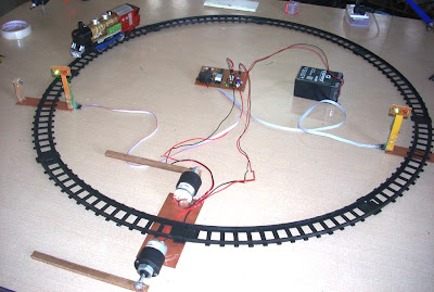
                 After a long delay, now again I am ready to post some interesting projects. Here I am sharing automatic Railway Gate control system using AVR micro controller. Gates will close automatically when train arrival and open when train departure from crossing. The main purpose of this project is to avoid accidents and save time.


This project utilizes Two IR Tx./Rx. Pair is placed at either side of the gate with some distance as shown in the pic above. When train cuts first sensor light signal toggled from Green to Red; a buzzer gets activated for 2 seconds and railway gate will closed. When train cuts second sensor then a countdown timer starts and when it counts zero light signal again toggled from Red to Green ; again buzzer gets activated for 2 Seconds and gates will closed. Timing for countdown timer is set in the controller according to the speed and length of the train. You can easily measure this timing for your toy train. I made this bidirectional so train’s direction doesn’t matter.

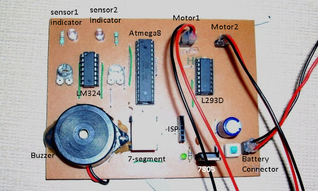
I design circuit using AVR ATmega8 microcontroller.IR sensors output is connected to comparator LM324.LM324 generates TTL High/Low signal at its output pins which is fed to MCU's pins as Input. According to input from LM324 Micro-controller take action. Two DC Motors is used for controlling the gate, these motor's current requirement is much more then MCU hence we need a Motor Driver IC L293D.

Required Components:
1.DC Geared Motors RPM:30 - 2
2.IR Tx./Rx. Pairs - 2
3.MCU ATmega8 - 1
4.IC-LM324 - 1
5.IC-L293D - 1
6. Registers 470E - 10,10K-2,4.7K-1
7.Capacitors : 1000uF.16volt -1 , 100nF-1
8.Seven Segment CC - 1
9.Some LED's : 2- Green, 2-Red, 3 others
10.7805 -1
11.6Volt,4.5MAh Battery
12.some wires, burg strips etc. 

and a Toy Train --


Circuit Diagram:


Making:
step 1 : First make the sensor setup.IR Tx./Rx. should be connected in line of sight. Two signal LEDs. Total five wire comes out from this sensor setup- VCC, GND, Sensor Output, Red LED anode, Green LED anode. Distance between IR Tx./Rx. is about 12cm.


Sensor Setup - 1


Sensor Setup - 2

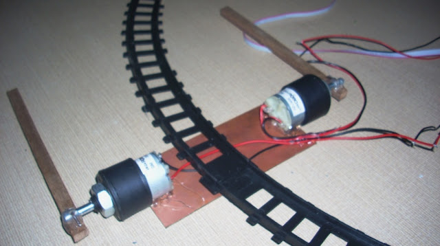
Step:2 Gear Motor's setup.


Step:3 Circuit design. I design the layout in PCB-Wizard.


Step:4 Whole setup -


See Video for more clarification.

Software : source code is written in C. MCU - Atmega8 @1MHz internal.Compiler - WINAVR.

#define F_CPU 1000000UL
#include <avr/io.h>
#include <util/delay.h>

#define CUT1 bit_is_clear(PIND,0)
#define CUT2 bit_is_clear(PIND,1)

#define BEEP PORTD|=(1<<PD4);\
delayms(1500);\
PORTD &=~(1<<PD4);\

#define MOTOR_CW PORTC = 0B00111010;\
delayms(800);\
PORTC=0X00;\

#define MOTOR_ACW PORTC = 0B00110101;\
delayms(800);\
PORTC=0X00;\

#define RED_ON  PORTD|=(1<<PD6);\
PORTD&=~(1<<PD7);

#define GREEN_ON PORTD|=(1<<PD7);\
PORTD&=~(1<<PD6);

char seg[10]={0x3F,0x06,0x5B,0x4F,0x66,0x6D,0x7D,0x07,0x7F,0x6F};

void delayms(uint16_t ms){
  while(ms){
    _delay_ms(1);
    ms--;
  }
}

int main()
{
DDRC = 0xFF;//All Outputs
DDRB = 0xFF;//All Outputs
DDRD = 0XF0;//PD0,PD1 Inputs,PD4-PD7 Outputs
PORTD|=(1<<PD0)|(1<<PD1);//Internal Pull Ups

int i,done;
while(1){
   done=0;
   GREEN_ON;
   PORTB=0X00;//Segment OFF

    if(CUT1){
    BEEP;
    while(CUT1);
    while(!CUT2){RED_ON;if(!done){MOTOR_CW;done=1;}}
    if(CUT2){for(i=9;i>=0;i--){PORTB=seg[i];delayms(700);}
    BEEP;GREEN_ON;MOTOR_ACW;
      }
    }

    if(CUT2){
    BEEP;
    while(CUT2);
    while(!CUT1){RED_ON;if(!done){MOTOR_CW;done=1;}}
    if(CUT1){for(i=9;i>=0;i--){PORTB=seg[i];delayms(700);}
    BEEP;GREEN_ON;MOTOR_ACW;}
    }
  }
 return 0;
}


After making this project I realize some limitation, first it required different type of IR sensors which should not detect human interrupt and second thing is at gate closing time if any vehicle present in between and below the gate then gate should detect the presence of any vehicle or obstacle. If you resolve these then please share.


                    circuit diagram

Video:
                                                                                                                ~Pratyush

PID Controlled Self balancing Robot using ESP8266 and MPU6050

This ROBOT is made using ESP8266 Node MCU and MPU6050 accelerometer. Motor used here is normal gear motor of 150 rpm with TB6612FNG motor dr...